- 您现在的位置:买卖IC网 > Sheet目录1200 > BP7B-LB (Powerex Inc)KIT DEV INTERFACE FOR IPM
�� �
�
�BP7B� Circuit� Explanation:�
�J2�
�IC6�
�VLA106-24154/VLA106-24151�
�VLA106-24154�
�40�
�39�
�38�
�R3�
�R2�
�IC1�
�1� 2� 3�
�IC12�
�8� 9� 10� 11�
�16� 17�
�37�
�36�
�35�
�LED4�
�F� O�
�W� N�
�+�
�C5�
�LED5�
�R4�
�+V�
�34�
�33�
�32�
�V� N�
�U� N�
�B� R�
�J1�
�VLA106-24151�
�27�
�IC2�
�R1�
�V� N1�
�V� N�
�+�
�IC5�
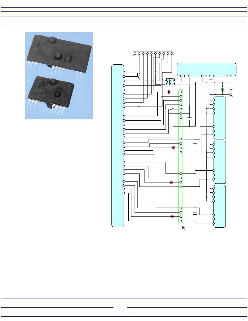
�Figure� 2:� Isolated� DC� to� DC�
�Converters� for� IPM� Control� Power�
�26�
�25�
�24�
�23�
�22�
�V� WP1�
�C4�
�A� complete� schematic� of� the�
�BP7B� interface� circuit� is� shown� in� figure�
�3� and� the� bill� of� materials� is� given� in�
�Table� 2.� This� circuit� uses� the� VLA606-�
�01R� to� transfer� logic� level� control� signals�
�between� the� system� controller� and� the�
�IPM.� The� internal� optocouplers� provide�
�galvanic� isolation� to� completely� separate�
�the� controller� from� the� high� voltage� in�
�the� power� circuit.� The� BP7B� also�
�18�
�17�
�16�
�15�
�11�
�10�
�9�
�8�
�4�
�3�
�LED3�
�LED2�
�W� P�
�WF� O�
�V� WPC�
�V� VP1�
�V� P�
�VF� O�
�V� VPC�
�+�
�C�
�+�
�C2�
�IC4�
�provides� isolated� control� power� supplies�
�to� power� the� IPMs� built-in� gate� drive� and�
�protection� circuits.�
�2�
�1�
�The� six� main� IGBT� on/off� control�
�signals� (U� P� ,V� P� ,W� P� ,U� N� ,V� N� ,W� N� )� are�
�transferred� from� the� system� controller� to�
�the� IPM� using� the� VLA606-01R.� The�
�IPM’s� active� low� control� inputs� are�
�LED1�
�V� UP1�
�U� P�
�UF� O�
�V� UPC�
�+�
�C1�
�IC3�
�pulled� high� by� the� VLA606-01R.� An� on�
�signal� is� generated� by� turning� on� the�
�internal� optocoupler� to� pull� the� IPM’s�
�J3�
�L-Series� IPM�
�Connector�
�control� input� pin� low.�
�The� brake� IGBT� control� signal� (BR)� is� transferred� from� the� controller� to� the� IPM� using� a� low� speed� opto-�
�coupler� (IC1).� The� active� low� brake� input� pin� on� the� IPM� is� normally� pulled� high� by� R1.� When� the� BR� control� line�
�(Pin� 6� of� CN1)� is� pulled� low,� current� flows� in� the� LED� of� the� brake� isolation� optocoupler� turning� on� its� output� and�
�pulling� the� IPM’s� brake� pin� low� to� activate� the� brake� IGBT.� If� the� IPM� being� used� does� not� have� the� brake� option�
�then� IC1,� R1,� and� R2� can� be� omitted.�
�The� IPM’s� fault� output� signals� are� transferred� back� to� the� system� controller� using� low� speed� optocoupled�
�transistors� internal� to� the� VLA606-01R.� During� normal� operation� the� fault� feedback� line� (pin� 9� of� J2)� is� pulled�
�high� to� the� +V� L� supply� by� the� 4.7K� resistor� R3.� When� a� fault� condition� is� detected� by� the� IPM� it� will� immediately�
�turn� off� the� involved� IGBT� and� pull� its� fault� output� pin� low.� The� IPM’s� fault� output� has� an� open� collector�
�characteristic� with� an� internal� 1.5k� ohm� limiting� resistor.� Current� flows� from� the� +15V� local� isolated� supply� to� the�
�low� speed� optocoupler� LED� (inside� the� VLA606-01R)� and� then� to� the� IPM’s� fault� pin.� The� optocoupler’s�
�3�
�发布紧急采购,3分钟左右您将得到回复。
相关PDF资料
BPBS8B96CAP1
BPBS8B96CAP1 COVER KIT 96P
C1113/40
BOOT CIRCUIT BREAKER TOGGLE CLR
C1113/42
BOOT CIRCUIT BREAKER BACK OF PNL
C1113/43
BOOT CIRCUIT BREAKER BACK OF PNL
C14G32
FUSE 32A 500V 14X51MM CLASS G
C1Q 7
FUSE 7A 63V 1206 FAST C1Q
C1S 3
FUSE 3A 63V 1206 SLOW C1S
C20A2P-GFI
GFI CIRCUIT BREAKER 20A 240V
相关代理商/技术参数
BP7B-LS
功能描述:KIT DEV INTERFACE FOR IPM RoHS:否 类别:编程器,开发系统 >> 评估演示板和套件 系列:- 标准包装:1 系列:- 主要目的:电信,线路接口单元(LIU) 嵌入式:- 已用 IC / 零件:IDT82V2081 主要属性:T1/J1/E1 LIU 次要属性:- 已供物品:板,电源,线缆,CD 其它名称:82EBV2081
BP7C31BH
制造商:INTEL 制造商全称:Intel Corporation 功能描述:CHMOS SINGLE-CHIP 8-BIT MICROCONTROLLER
BP7C51BH
制造商:INTEL 制造商全称:Intel Corporation 功能描述:CHMOS SINGLE-CHIP 8-BIT MICROCONTROLLER
BP800-0.005-00-1212
功能描述:THERMAL TAPE 12X12" 0.005" 制造商:bergquist 系列:Bond-Ply? 800 零件状态:有效 使用:片状 形状:方形 外形:304.80mm x 304.80mm 厚度:0.0050"(0.127mm) 材料:丙烯酸 粘合剂:粘贴 - 双侧 底布,载体:玻璃纤维 颜色:铁灰 热阻率:- 导热率:0.8 W/m-K 标准包装:1
BP800-0.008-00-1212
功能描述:THERMAL TAPE 12X12" 0.008" 制造商:bergquist 系列:Bond-Ply? 800 零件状态:有效 使用:片状 形状:方形 外形:304.80mm x 304.80mm 厚度:0.008"(0.203mm) 材料:丙烯酸 粘合剂:粘贴 - 双侧 底布,载体:玻璃纤维 颜色:铁灰 热阻率:- 导热率:0.8 W/m-K 标准包装:1
BP80001-JCB59LF
功能描述:电缆组件 CFQ-7400 RoHS:否 制造商:Molex 产品:Power Assemblies 类型:Cable Assembly 连接器端口 A:No Connector 连接器端口 A 管脚计数:4 连接器端口 B:No Connector 连接器端口 B 管脚计数: 型式:Male 线规 - 美国线规(AWG):20, 28 长度:0.305 m 颜色:Black, Red
BP80005-JCB60
制造商:FCI 功能描述:591-23PF-MIXED TECHNOLOGY - Bulk 制造商:FCI 功能描述:OEM ITEM 591-23PF-MIXED TECHNOLOGY
BP80009-JCB61
制造商:FCI 功能描述:591-23PF-MIXED TECHNOLOGY - Bulk 制造商:FCI 功能描述:OEM ITEM 591-23PF-MIXED TECHNOLOGY